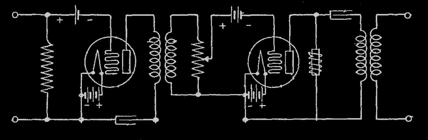
First of all a schematic is drawn, then built on a breadboard and checked. After many tests the amplifier will start to evolve. The described amplifier will be based around the following schematic and will employ 2A3 and E86C tubes.
Having the final schematic, the components that will be used are collected.
They are laid down and the first rough dimension measurements are done.
After designing the chassis with CAD software, a printout is taken and checked to ensure that the components fit.
Now it is time to send to the factory the DWG file to cut and bend the steel chassis.
Next the corners and the bottom rails ( that will support the bottom cover ) are welded and the chassis is brushed and chrome electroplated.
This is the chassis after cutting, bending, welding and electroplating and just before being painted with three layers of electrostatic coating.
Here is the chassis after painted with three layers of electrostatic coating.
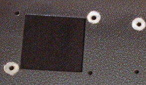
In this detail picture under the hood, you see the non coated areas for grounding and heat dissipation.
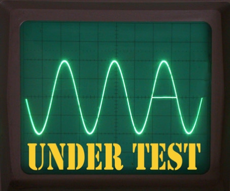
The 2A3 Amplifier is ready to undergo some heavy testing.
The amplifier has succeed to pass several tests, including the final one: burning @ 80 % of its rated output power for 24 hours continuously.